Allowing Google casting or mDNS between VLANs
If you’ve arrived here you probably just want a way to allow your devices to cast to your Chromecast and Google home devices when you have implemented VLANs and it no-longer works. This guide comes in 2 separate parts – The explanation of why mDNS doesn’t work in a multi-vlan arrangement and the how-to guide for creating a VM or container to resolve the issue. If you’re not interested in the why then skip part 1 and go to part 2.
Part 1: Why mDNS between VLANS is an issue
mDNS stands for multicast domain name system. This is a protocol used increasingly in smart home devices to resolve the ip address for a device or service on a local network. This service fails on a VLAN segregated network as the ‘on a local network’ portion is important here because each VLAN is considered to be a different local network. This can cause issues with services which rely on mDNS.
A prime example of how this can affect us is when it comes to casting from a device to a Google nest speaker or chromecast device. mDNS is used by these devices for discovery of devices to cast to and when our media devices are in one VLAN (Such as an IoT vlan) and our users are in another it can cause issues because it seemingly does not work.
A quick google shows multiple results claiming that the TTL on an IP packet for an mDNS query is set to 1. This means that at soon as the packet is received by the next hop (e.g. the default gateway when crossing the VLAN boundary) then the TTL is decremented and the packet is discarded. So lets confirm this expectation of the behavior. mDNS is defined in RFC 6762, this RFC says the following:
11.  Source Address Check

   All Multicast DNS responses (including responses sent via unicast)
   SHOULD be sent with IP TTL set to 255.  This is recommended to
   provide backwards-compatibility with older Multicast DNS queriers
   (implementing a draft version of this document, posted in February
   2004) that check the IP TTL on reception to determine whether the
   packet originated on the local link.  These older queriers discard
   all packets with TTLs other than 255.
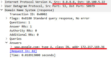
This conflicts with a lot of online sources that say the TTL is set to 1 for mDNS packets. So lets look at how google implements the RFC. To do this I took a wireshark capture of an mDNS query from a local device attempting to cast to a google mini. Lets look at a wireshark capture for one of these mDNS query:
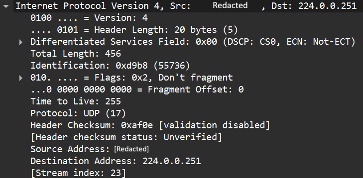
So the TTL is actually set to 255. This means that it is actually possible to route these packets. So what’s going on? To understand this behavior we need to go back to RFC 6762 which states:
   A host sending Multicast DNS queries to a link-local destination
   address (including the 224.0.0.251 and FF02::FB link-local multicast
   addresses) MUST only accept responses to that query that originate
   from the local link, and silently discard any other response packets.
   Without this check, it could be possible for remote rogue hosts to
   send spoof answer packets (perhaps unicast to the victim host), which
   the receiving machine could misinterpret as having originated on the
   local link.
So now we get to the actual issue – When the source of the request is in a different VLAN and the devices are RFC 6762 compliant – they will ignore all queries from the external VLAN as the TTL will be less than 255. So while the generally accepted explanation of the root cause on the internet is wrong – the effect is pretty much the same. Queries from a device in one VLAN are not serviced by a device in a second VLAN. So this tells us there isn’t a layer 3 solution to this problem as at the application level the RFC tells mDNS implementations not to accept anything from a different vlan. Therefore the only solutions have to be implemented within a layer 2 context and routing is not supported.
Part 2: Permitting mDNS across vlans using a VM or container
So now that we know that the mDNS packets will be ignored when they are sourced from a different VLAN we have only one valid solution: Implement a relaying device to relay messages between VLANs. You might think NAT could be used to spoof the IP to be that of the same subnet and it can – but the check isn’t source IP; It’s TTL.
This guide focuses on the second option. To resolve the issue we will implement an mDNS relay server. The concept is simple. We implement a Linux server which is a member on each VLAN we want to mDNS to work between.
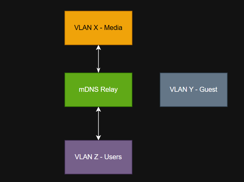
So we need a server with an interface/ip address in each vlan where we want mDNS to propagate, we want a service which can relay the mDNS packets/requests and we also don’t want to allow anything else. We may also want to ensure that we only allow the relaying on specific VLANs and not include things like the guest vlan.
Proxmox solution
This solution is ideal when you have a proxmox server on your network to which you are trunking all of the relevant VLANs to the host. The solution involves:
- Creating a container
- Installing the software to relay mDNS queries
- Add the container to all VLANs where relay is desired
- Lock down the containers firewall to only allow mDNS
Step 1 – Plan your setup
For this service we need to decide which VLANs we want to relay mDNS between and select an IP address inside every one of those networks. If we run DHCP on those networks we should create a reservation. Create a basic plan to match your home network (example below for illustration only
| VLAN ID | IP address | Purpose |
| 500 | 192.168.1.250/24 2001:db8:CAFE:1::250/64 | Servers* |
| 100 | 192.168.2.250/24 | Users |
| 666 | 192.168.3.250/24 | Media |
NOTE: All VLANs, VLAN IDs and IP addresses are purely for demonstration and should be changed to match your internal network.
Step 2 – Create a new container
Create your container using whichever Linux distro you prefer. In this example I recommend using Debian 13 or Ubuntu 24. Give it the following resources:
- 1 vcpu
- 128 MiB Ram
- 512 MiB SWAP
- 2 GB HDD (Assuming Debian 13)
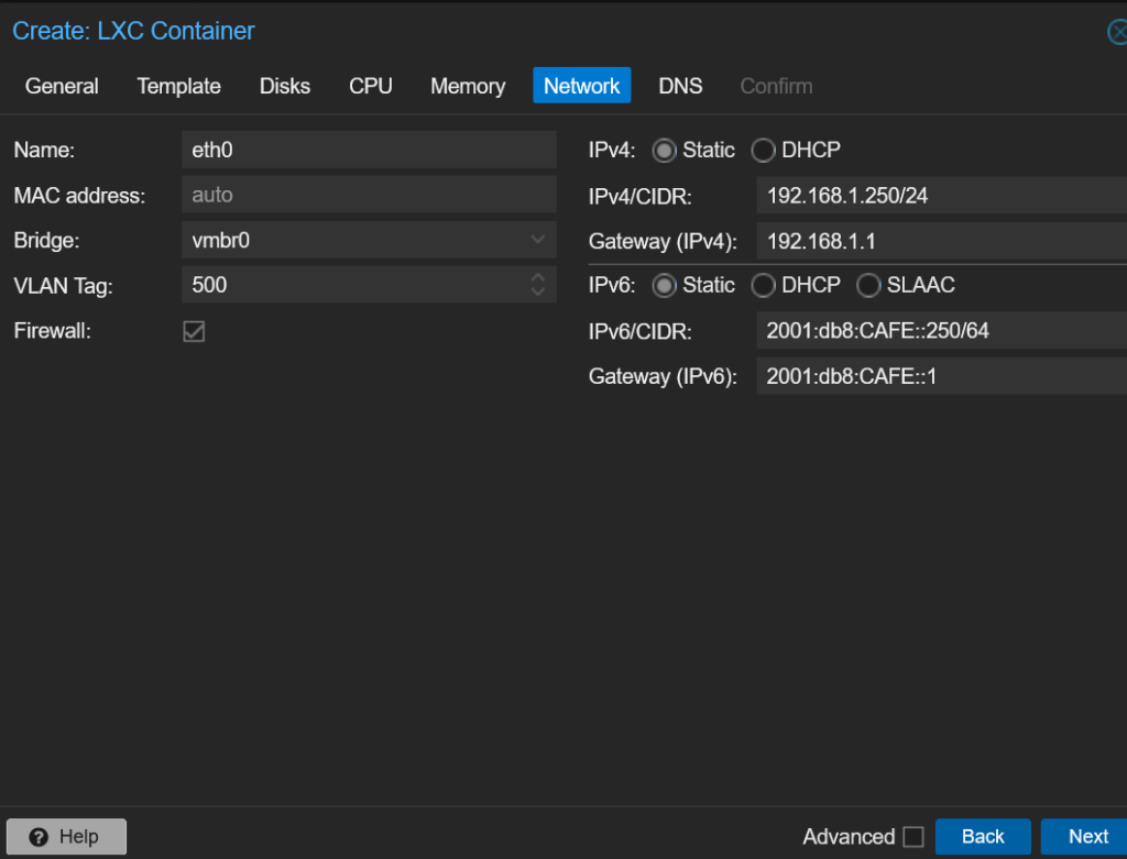
When it comes to network configure your main interface which you will use to have access to the internet from the container. IPv6 is optional but you must have a default gateway and internet access
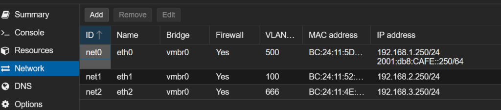
Next navigate to your containers network settings and add in the additional networks. Note that default gateway should be left blank for these networks:
Step 3 – Install the software required
After you have secured the container to your liking install the avahi-daemon software:
apt install avahi-daemonConfigure the software by editing /etc/avahi/avahi-daemon.conf
vim /etc/avahi/avahi-daemon.confUnder the [Server] block ensure that use-ipv4 and/or use-ipv6 are uncommented
[server]
use-ipv4=yes
use-ipv6=yes
And under the [reflector] block ensure enable-reflector is set to yet
[reflector]
enable-reflector=yes
If using UFW then permit the mDNS packets in your chosen VLANs and to/from the multicast addresses. If using the proxmox firewall mirror the same rules. Since the servers functions are basic we can completely lock it down to only relay mDNS.
ufw allow from 192.168.1.0/24 proto udp to any port 5353
ufw allow from 192.168.2.0/24 proto udp to any port 5353
ufw allow from 192.168.3.0/24 proto udp to any port 5353

ufw allow to 224.0.0.251 proto udp to any port 5353
ufw allow in 224.0.0.251 proto udp to any port 5353
ufw allow in proto udp to 224.0.0.251
ufw allow in proto udp from 224.0.0.251
ufw allow in proto udp to ff02::fb
ufw allow in proto udp from ff02::fb
Finally enable avahi-daemon and restart the service:
systemctl enable avahi-daemon
systemctl restart avahi-daemon
The server is now setup to automatically relay mDNS
What if i use a different hypervisor/bare metal server/VM?
The process is the same, Create a VM or container with an interface in each VLAN and install the software as before.
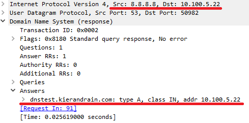
Bonus information: Google device internal DNS issue
Unrelated to mDNS – An important thing to know when troubleshooting google devices is that they will often ignore DHCP issued DNS servers and instead use Google DNS (e.g. 8.8.8.8, 8.8.4.4) instead. This can cause issues when resolving DNS internally and sometimes cause issues when using services such as TTS from Home assistant to device to fail to send. There is no way to over-ride this behaviour from the google device but NAT could be used at the network level to over-ride the DNS requests going to google.
Note: This can cause other issues and is not necessarily recommended.